Smart charging at home, and more
Posted by Harm Otten in Heating, Self Sustaining, Solar energy 37 Comments» Do you want to charge your electric car solar based, or when the electricity tariff is low? Do you want to turn on your central heating before you come home? This article describes how I realized it, and more, at low costs.
Introduction
Until now, it was always a bit tricky while charging my car at home and using other high power equipment at the same time. Why? Because the connection from the grid to my home is a three-phase connection, and like many households it is limited to 3x25A. While charging the car at 3x16A, only 9 Ampère per phase is still available for the rest of the house. Even a water cooker using 10A can be tricky then. Therefore, one of my goals is to protect the main fuse from overcurrent, by automatically throttling down the charging process or when necessary, pause the charging completely.
Secondly I want to be able to charge the car in a smart way. With “smart” I mean, let the charging speed automatically be determined by the available solar power, or charge at minimum costs. This also stabilizes the grid and allows more room for renewable energy.
Furthermore, I want to be able to remote control my central heating. And this remote access needs to be secure, of course.
Finally, I added a Particulate Matter sensor to measure the amount of PM10 and PM2.5 outside. This gives me some insight of the outside air quality. This information could be used to control future ventilation systems.
Determine technology
During the design process, I made several decisions about what technology I will use. It has to be flexible, easy to maintain, secure, low power, and preferably not expensive.
As I do not want many wires crossing my house, I started to investigate what wireless technic to use. There are lots of standards to choose from, but they all have their advantages and drawbacks:
– rfxcom (433.92 MHz)
– Zigbee (2.4 GHz)
– Z-Wave (868.42 MHz)
– WiFi (2.4 / 5 GHz)
(General remarks: The lower the frequency, the longer the antenna. The higher the frequency, the shorter the range, but more bandwidth is available.)
Rfxcom is a bit older technology, and the number of devices I found were limited.
Zigbee is an Open standard, but not every manufacturer follows the standard precisely. In some cases I read, it lacks security, and one device in your network can be the weakest link for the rest.
Z-Wave is greatly depending on one manufacturer [Sigma Designs] that does the certification of all the devices. This is good for keeping the quality high, but not so good for the price and broad usage.
Both Zigbee and Z-Wave support a mesh network. This enables the communication to go from one node to another, which can be an advantage when one device could otherwise not reach the main access point by itself. (https://en.wikipedia.org/wiki/Mesh_networking)
Finally I ran into boards based on ESP8266 chips. They use WiFi, come in many shapes and configurations, are very cheap, easy to use, and have many possibilities. There is even a software library available that, if used, can make a mesh-network of all these WiFi devices. WiFi is optimized for high data throughput and not for very low power, but these boards have so many advantages that I decided to use this wireless communication technic anyway. It depends of course on what you define as low power. One device based on an ESP8266 chip uses about 10Wh per day, which is less then 4kWh per year. (More info on this power usage)
What hardware?
I already have a Raspberry Pi running for some other tasks, but still it has lots of capacity unused, so I figured, this Pi can easily function as a domotics server as well.
As I decided to use my already available WiFi network for wireless communication, I do not need to install an extra antenna for my Raspberry Pi to support rfxcom, Zigbee or Z-Wave.
I have the following energy meters:
– Smart meter for Electricity and gas (P1-Port)
– Solar Gross Production Meter (S0 pulse counter)
– kWh meter of the chargebox (S0 pulse counter)
– Water meter (Analog counter)
For reading all these meters I decided to use a WEMOS D1 R2 Mini. This board is based on the ESP8266 chip, has several input/output possibilities, is fed by a micro-USB connector, and cost only around €2,50.

To power it, you just need a micro-USB power supply, which you may have laying around somewhere, and if not, you can get them at many shops.
To communicate with my chargebox I will use a similar board, but I will come back to that later.
Energy metering
Smart meter
To be able to keep the current of the 3 phases within its limits, you first need to measure it. Normal households in the Netherlands have either 1 phase 35 Ampere (1x35A), or 3 phase 25 Ampere (3x25A) connection. There are different types of smart meters installed in the Netherlands, and I happen to have one of the “older” types that does not measure Currents. So I started to investigate if I could measure these Currents myself. But I soon discovered that for 3 phases it is not going to be easy. A lot has to do with taking into account different power factors and current being able to flow both ways. That did not stop me from trying, but I also do not want to overcomplicate things. So I managed to get a new smart meter from Enexis with DSMR 5.0 (Dutch Smart Meter Requirements), which can do it for me! This meter has all the data I need present at its P1-port, which is in fact a read-only serial port.
Although a WEMOS has a serial port available, first the voltage of the signal has to be converted from 5 to 3.3V and the signal also needs to be inverted. So some extra electronics is needed to do that. Actually, all input signals to the WEMOS also needs to have some protection and filtering circuits to keep interference signals outside. Soon I found myself creating an electronic design around the WEMOS. For this I found myself the perfect online tool: EasyEda. It has libraries of almost all electronic components, it is free of use, and you can even convert your schematic into a Printed Circuit Board (PCB).
This is the input-schematic I used for the connection of the P1-port:
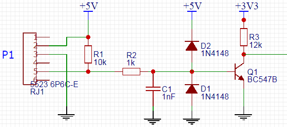
You need to apply 5V to pin2 of the P1-port to ask the smart meter for data. R2, C1, D1 and D2 is for protection and filtering. This is very important, because you want to get rid of all kinds of interference signals. Finally the signal from pin5 of the P1-port is inverted by the transistor and also converted to 3.3V.
Pulse counters
Both my [Solar Gross Production Meter] and the [kWh meter of the chargebox] have a S0 pulse output. For these signals I created the following schematic:
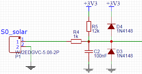
To invert the signal and make it “clean”, I added a Schmitt-trigger between the input schematic and the WEMOS:

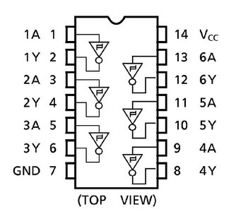
I used a SN74HC14N which has six in one package, which is plenty for this PCB.
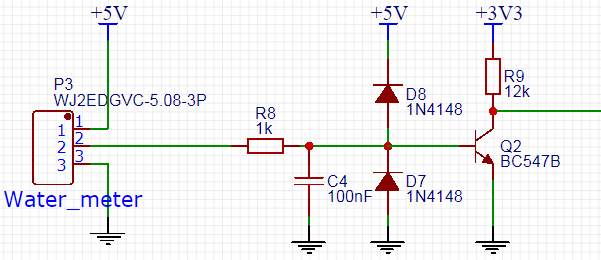
Water meter
For the analog water meter I needed to make something special. I could of course buy some ready-made sensor in a shop for about €80, but all I need is just a proximity switch sensor for €3,50, that operates on 5V, and mount it with a 90mm pipe bracket above the metal part of the small wheel that turns once every liter, to create my own digital pulse counter. This is the result:
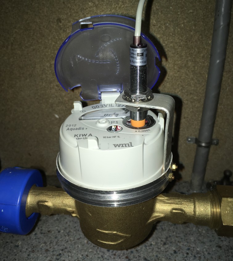
And again a similar input circuit that transforms the signal to make it suitable for the WEMOS:
The reading of the water meter is not necessary for this project, but a nice to have.
Energy metering combined
Finally I designed a layout of all the components on a prototype PCB, and this is the result:

What software?
Hardware that contains microcontrollers is nothing without software. So I need software on the Raspberry Pi (Server), and on the small WiFi devices (Clients) as well.
Server software
Domoticz seems like a logical choice to run on the Pi. It has lots of possibilities, and the list of compatible devices is very long. Nevertheless, thanks to a very convincing demonstration by a good friend, I chose Node-RED to be the heart of the system. With this open-source tool I can be more flexible, and program everything exactly the way I want it. It has a nice intuitive web-based interface, with lots of example flows to choose from.
Besides Node-RED being the heart of the system, a dashboard layer is also available. This dashboard presents itself as a web application, and is also very suitable for mobile devices, like a smartphone. This way, you even do not need an App on your phone, just a browser will do!
Furthermore, I installed database MariaDB. This is a fork of MySQL, and is therefore very similar to it. But where MySQL has a down-trend in google-searches, MariaDB has an up-trend. And it being open-source, made me decide to use MariaDB.
To maintain the database there are also many possibilities. But I choose to use phpMyAdmin, which can also be installed on the Raspberry Pi, and has a nice intuitive web interface, just like Node-RED.
Finally I want to make the data visual in the form of charts. For that I found this nice open-source software Grafana.
Client software
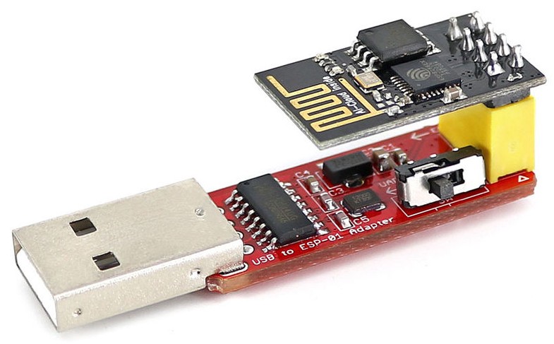
The software that runs on the clients, in my case WEMOS and ESP-01 devices, is programmed in the language C++. A nice Integrated Development Environment (IDE) is available for programming and uploading the software to the devices. It is called Arduino IDE and it is available for several operating systems. (More info)
You need to connect the client-device to your PC, if you want to upload your software. For a WEMOS you only need a micro-USB cable, but for an ESP-01 you need this nice little (cheap) programmer:
I created the software for reading all the energy meters myself. As this was the first sketch (name of a program in the Arduino IDE) I made, I had to start with programming the basics: Connecting to WiFi and my MQTT-broker, receiving the current time from the internet to set the internal clock (taking into account summer and wintertime), configuring all the I/O ports including the serial port which I will use for getting the data from the P1 port, decode the smart meter P1-telegram and its CRC-code, create interrupt-routines for the three pulse-counters, and send all the gathered information by MQTT-messages to Node-RED!
Later on, I even programmed my devices in such a way that I can upload new versions of the software over the air (OTA), which makes it very convenient, because then you do not have to get the device and connect it to you PC anymore.
Chargebox
Currently I have a chargebox of the brand EVBOX in my garage. I chose for this box in 2013, because back then they said, it would probably be possible in the future to do smart things with it. Unfortunately now it seems I need to buy an expensive upgrade for it, if I want to use the smart-options.
Because I already knew there was a connection in my EVBOX available to connect multiple boxes and do load-balancing, I thought to myself, then it must somehow be possible with the current hardware to do smart-charging also. In a schematic of the box I discovered this connection was a RS485 bus. So I asked the company for some technical documentation about this bus, but unfortunately they would not share it with me. And that’s where the challenge started…
I mean, how hard can it be to reverse engineer the protocol myself? Well, this is what I did.
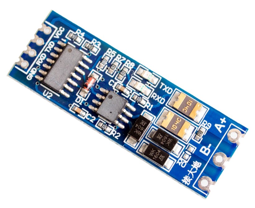
I bought the following hardware. First, a RS485-to-serial converter:
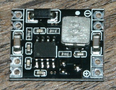
Second, a 12 to 3.3V converter (There is a 12V connection available inside the EVBOX):
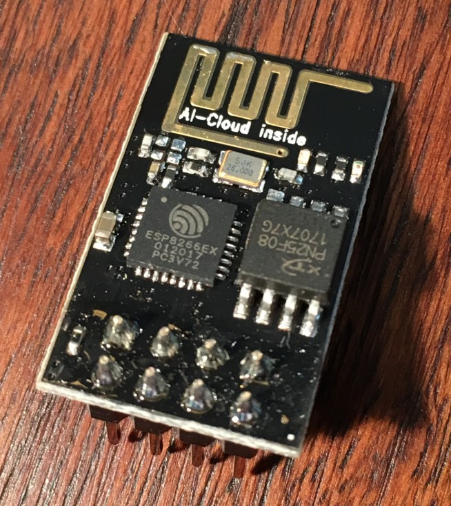
Third, an ESP-01 (this is a small board based on the ESP8266 chip which runs on 3.3V):
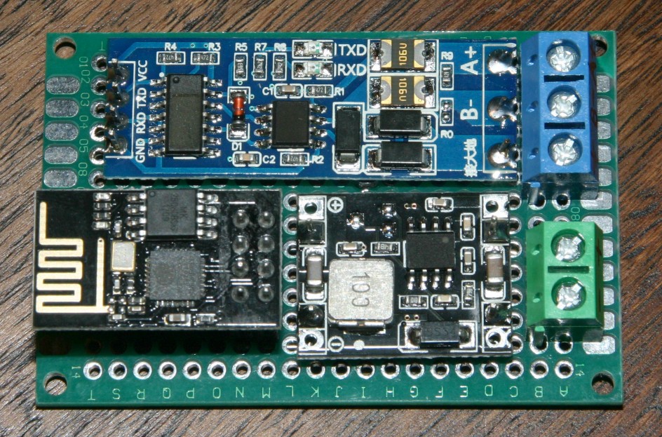
Total cost is below €4 and I put these together on a small PCB:
Then I took the following 7 steps:
1. Determine baud rate of serial data
To be able to read data, you first need to know at what baud rate it communicates. So with the help of a friend, I wrote a small test program that measures the time between digital ones and zeros, uploaded it into a WEMOS and started listening on the serial port. It seemed the smallest pulse was about 26µs. With this info you can calculate that the maximum baud rate must be 38k4 bits/sec.
2. Discover serial parameters
This step took a bit more time. First I uploaded esp-link on the ESP-01. This is a tool that converts the serial data to WiFi. I set the baud rate to 38k4 and tried some serial settings (data/parity/stop). But no matter what I tried, the data made no sense at all.
Then after some time I started to investigate the raw data, and finally I came to the conclusion that the serial signal was inverted! The ESP-01 has a hardware serial port build in, but that does not have the option to invert the signal. By using a software-serial port I finally could read some data.
Serial settings: 8N1 (8 databits / No parity / 1 stopbit)
Data consists of plain ASCII which represent hexadecimal data.
3. Inverted the serial signal
To invert the serial signal, I switched the RS485 wires.
This has a big advantage, because now I can use the hardware-serial port.
4. Investigate data structure.
Now comes the hardest part, figuring out what the data means. So I created a spreadsheet, and started logging the data, while I gave commands to the chargebox.
I started to recognize commands, and figured out how the checksums were calculated.
5. Sent first command
Until now I only listened on the bus, but to influence the charging process, I must be able to send commands too.
So I tested a simple command: Turning on and off the LED-ring of the chargebox. It worked!
So two-way communication is working correctly.
6. Programming ESP-01
I removed the esp-link-software and programmed a nice interface inside the ESP-01 myself that handles the checksums, recognizes complete commands and sends them to Node-RED via MQTT, and vice versa.
7. Change maximum charge current
I can now start and stop the charging via commands in Node-RED, which is nice. But one very important part is still missing. I want to be able to change the charge current while charging is in progress. That is, after all, the reason why I build this interface!
But I do not know the command for it, and the Customer service of EVBOX will not help me in providing these technical details. Or will they…
I came up with a plan. I started logging the raw data on the bus, connected my car with the charge cable to the chargebox, and called the EVBOX support. I know they can remotely configure the maximum charge current. So I asked them, if my chargebox was configured at the maximum possible charge current. They responded with: “Yes, at 16 Ampère”.
“Ok”, I said. And then I asked, “Just to be sure, can you temporarily set it to 15A?”
They did, and that was exactly wat I needed!
I asked them to put it back to 16A, and thanked them extensively ;-).
This was the last piece of the puzzle, and without them knowing, they helped me find it.
I wonder what will happen when they will read this article someday, but then again, it is my chargebox, and I can do with it what I want.
Smart charging
Now that I have the interface to my chargebox operational, I can start programming the smart stuff in Node-RED.
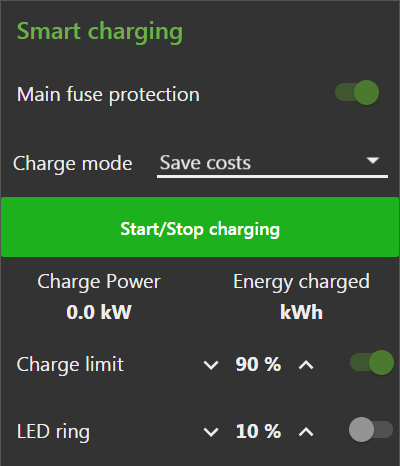
The first option is the Main fuse protection. In my case the chargebox has a 3-phase connection, so I have to check all three phases of the main for possible overcurrent. In case the current of one of the phases is too high for the main fuse, the charging speed needs to be reduced. The electricity meter sends its data every second to the server, and the main fuse(s) are of the slow-type, so there is plenty of time to react. Furthermore, the Renault ZOE needs a minimum current to charge, so if the charge current would need to drop below this threshold, the charging needs to pause temporarily.
Next selection is the Charge mode. I defined the options: “Direct”, “Save costs”, and “Solar based”.
“Direct” will start the charging immediately.
“Save costs” will charge the car only when the electricity tariff is low. Currently I have only a high or low tariff, but that might change in the future.
“Solar based” will only charge the car when the solar panels produce a certain amount of power. The Renault ZOE charges at three phases and needs a current of at least 12.5A. That means 3*12.5A*230V = 8,6kW is needed. But the inverter of my solar panels can only produce a maximum of 2.6kW on one phase only. This means, apart from the available solar power, extra power from the grid is always needed during charging. I could improve this by switching to one-phase charging, but this needs some hardware changes, which I might implement in the future.
Central heating
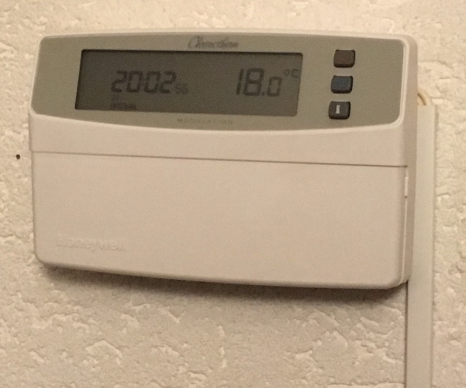
Nowadays there are several “smart” thermostats for sale that allow you to remotely adjust the temperature in your house. The disadvantage is that they are costly, and introduce another separate system. Apart from that, my current thermostat is still working fine. It only lacks a remote interface.
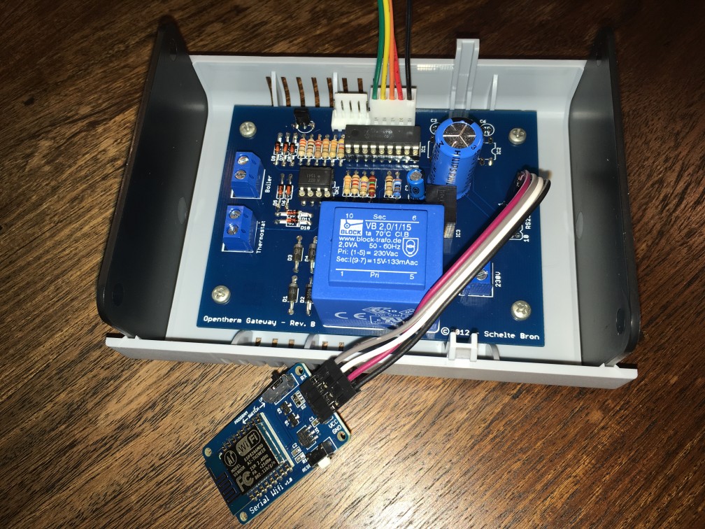
Then I ran into a nice do-it-yourself (DIY) project that describes how to make an Opentherm Gateway (OTGW). This device connects between your thermostat and the central heater. It allows you to monitor the data, and override the temperature settings. Fortunately my current thermostat is of the Opentherm type, so I decided to go for it.
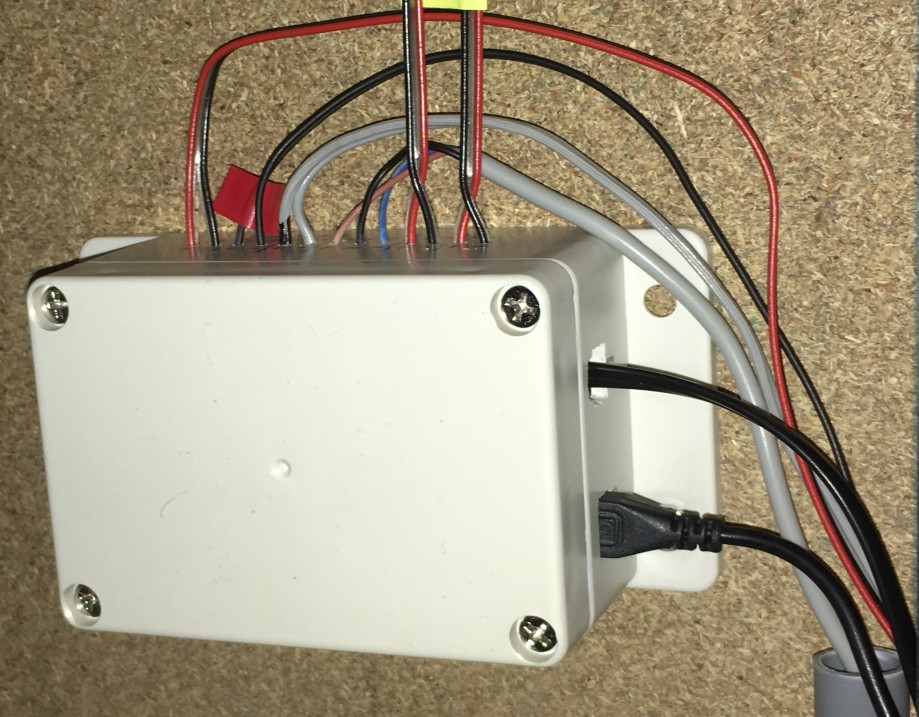
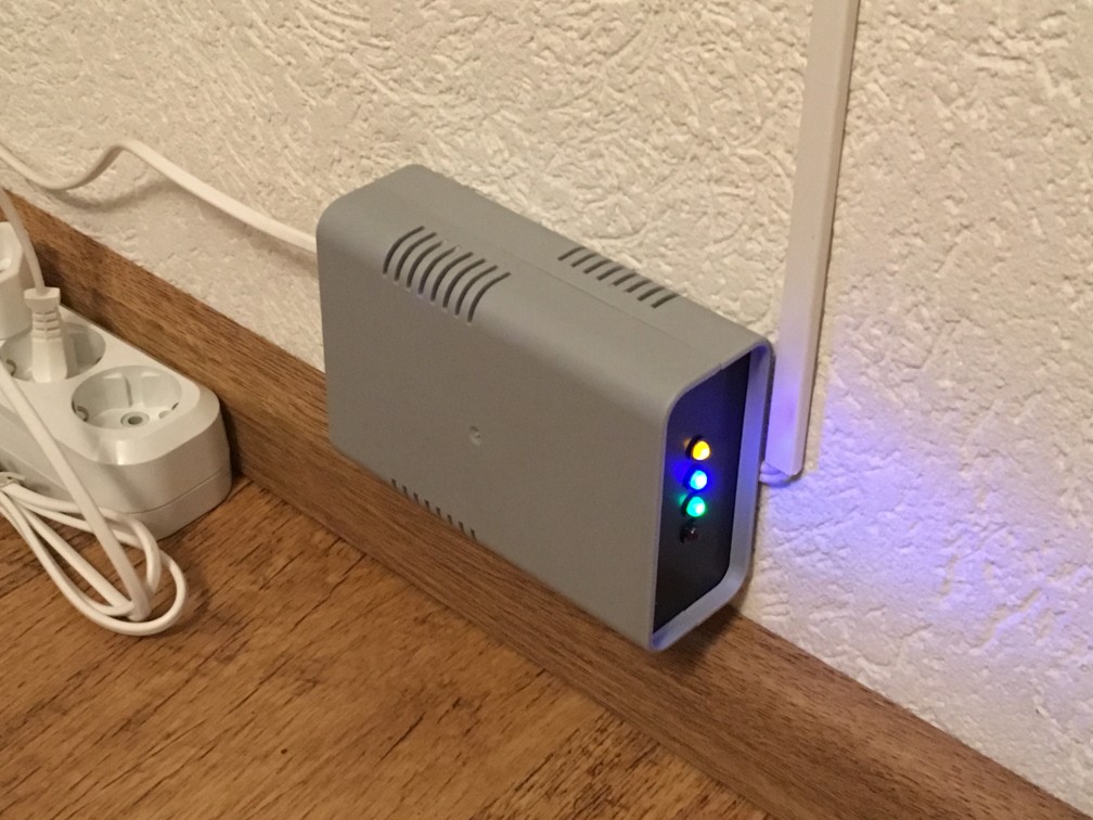
I ordered all the necessary parts, programmed the PIC-chip, replaced the standard serial interface with a wireless one using a small Serial-Wifi ESP8266 board, installed esp-link on it, soldered the components on the PCB, and build it in a case. This is the result:
On the outside of the case there are 4 LEDs, which can be programmed. I chose four different colors: yellow, blue, green and red, and gave them the following meanings:
Yellow: central heating active
Blue: Domestic hot water heating active
Green: Thermostat override
Red: Error
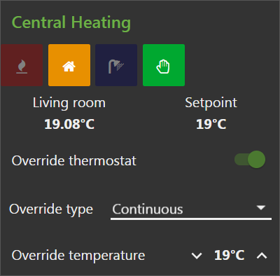
Last but not least I created a flow in Node-RED using the wireless data of the OTGW, which resulted in the following interface that allows me to (remotely) monitor and control the temperature at home:
Security
First I used the Node-RED dashboard only within my local network. But to be able to use it remotely, security needs to be in place. That means an encrypted connection via HTTPS is needed. For this encryption you need a certificate, which I found at this provider for free:
Let’s encrypt
Then you need a domain that links to your home, and check if your hope IP-address is static or dynamic. The certificate needs to be installed on the server running the dashboard, a strong password in Node-RED needs to be set, and a mechanism to renew the certificate is necessary, because otherwise it will expire after some time. Finally your router needs to be configured to forward the traffic to the correct place.
This was definitely not easy to implement, but crucial for creating a safe remote interface.
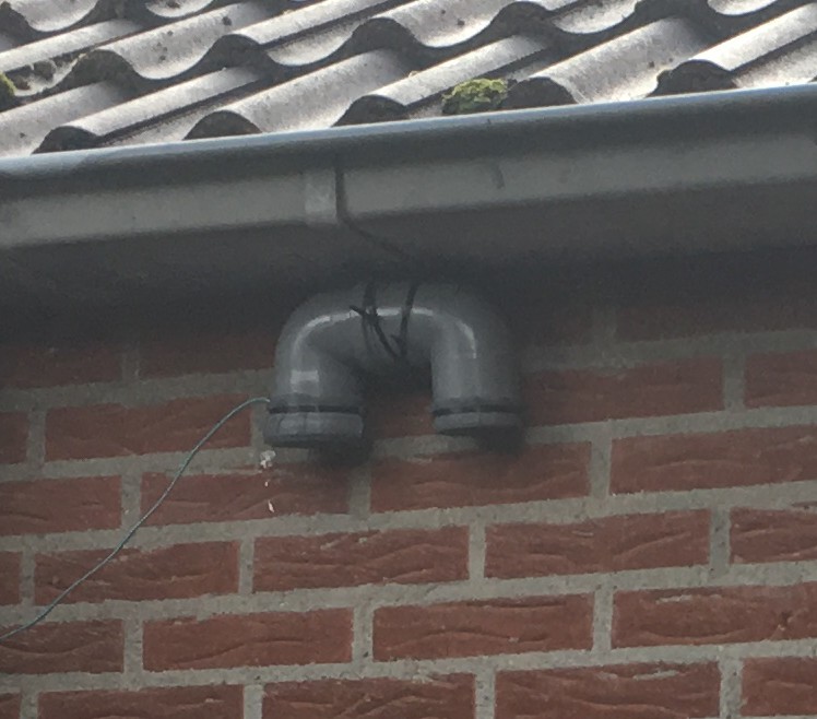
Particulate Matter sensor
On a German website there is a nice manual of how to build a Particulate Matter sensor yourself for under €30.
It can send its data automatically to a public website.
But I also store the data locally, so I can make my own charts.
Future
Electricity provider with prices per hour
In the future there are possibilities for having different prices every hour at your home address. Currently there is one provider that offers this:
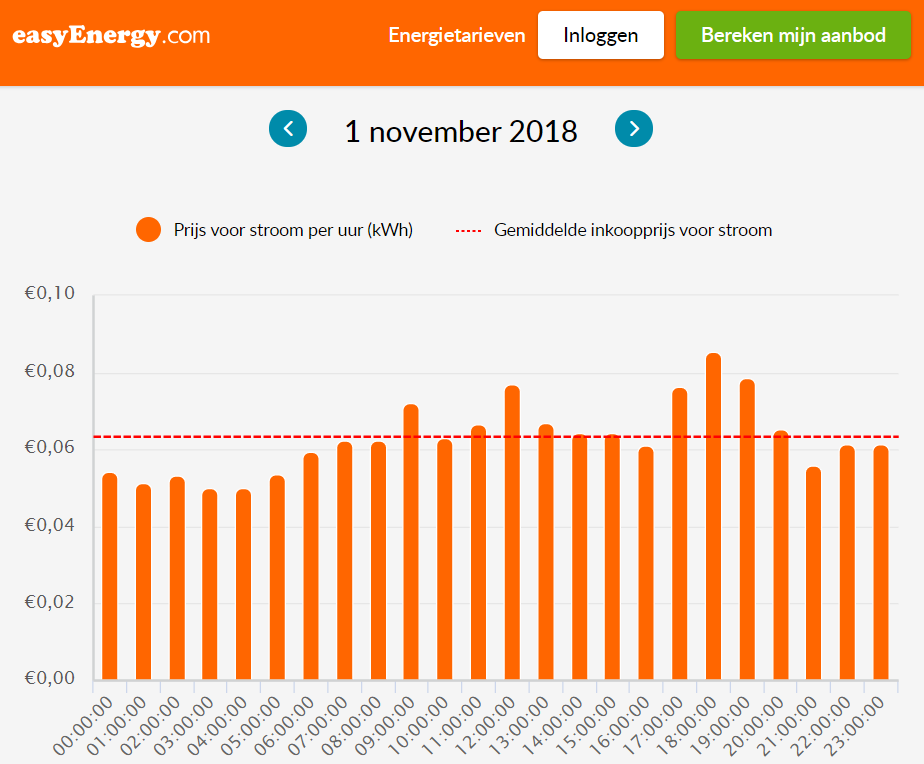
But I think there will be more providers like this in the future to choose from.
As the prices are available one day upfront, you can automatically charge the car or do other energy-hungry actions when the prices are low, or maybe push excessive energy back into the grid when the prices are high. This will save you money and balance the grid at the same time.
Home battery and Vehicle to grid
Currently I can only charge the battery of my car, but I want to be able to get energy out of it too (V2X – Vehicle to everything). And when the car is not present, a home battery can be that buffer.
Heat pump
Somewhere in the near future I want to get rid of the expensive gas connection to my house. Therefore the current central heating system will be replaced by (most likely) a heat pump system. This will also have an impact on the Opentherm Gateway.
CO2 controlled ventilation system
To create a better climate indoors, I want a ventilation system that is controlled by the amount of CO2 in the air. Furthermore it needs a heat exchanger to make it energy efficient.
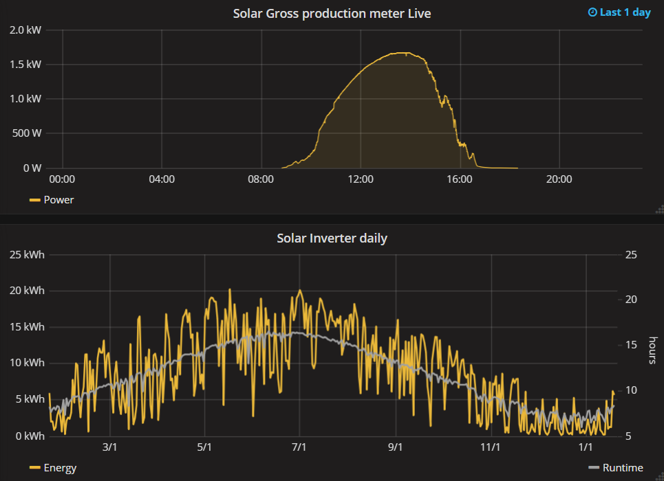
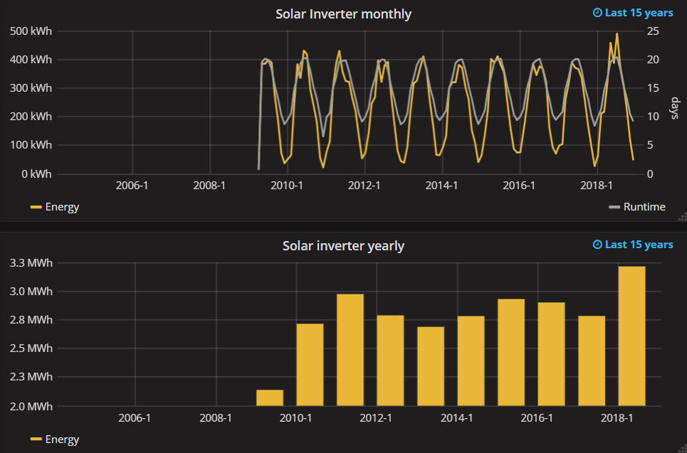
Charts
Finally I want to present some charts created by Grafana. These give a nice inside of what data is currently collected.
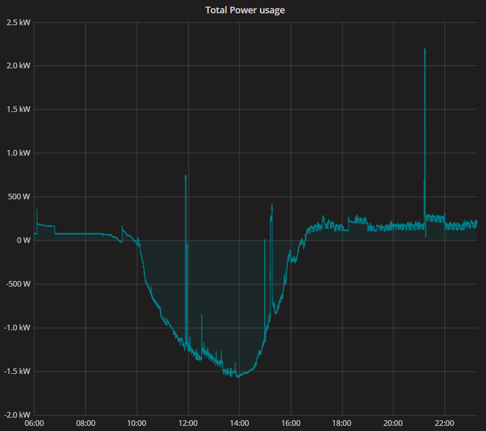
Solar charts:
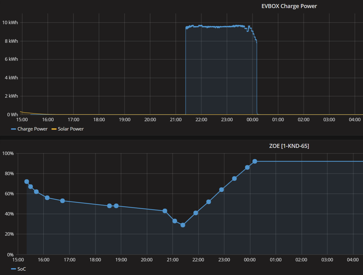
Charge Power and State of Charge:
Central heating and Gas usage:
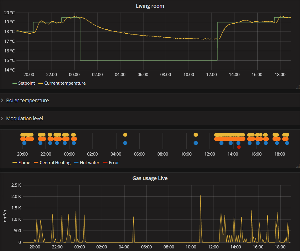
Water usage:

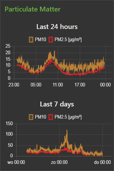
Particulate Matter:
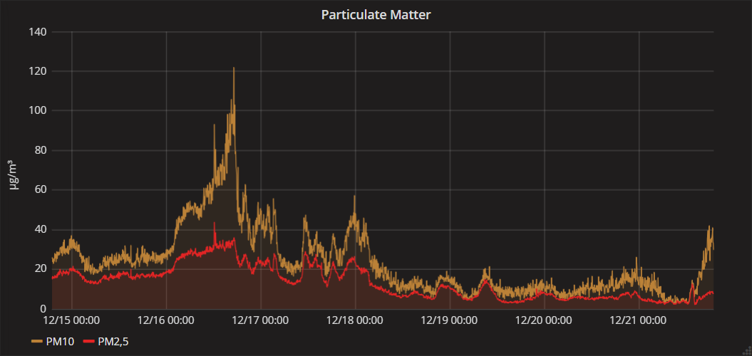
(According to European standards for PM10, the upper assessment threshold of a daily average is 35 µg/m³)
Lamp Portal


Oil Price
WTI Crude Oil

37 replies on “Smart charging at home, and more”
@Harm: thanks for sharing your smart-charging solution. But can the source code for the various devices be attached to this article (preferable hosted)? This could be motivating to readers to build such project themselves, even when they are not as skilled in programming/developing software.
Whoa! What a detailed insight on Smart charging at home, and more. Solar energy is being used in most of the countries and it is not stopping there, the usage of solar energy is increasing day by day and I must say I’m pretty sure soon solar will be used in our day to day lives. Your blog is amazing and it helped me understand some basic info regarding how one can smartly charge their phones. I’ll share this blog with my friends and thank you for posting this blog.
@ Harm: great work what you have done. I have bought a EV BOX (1 fase) from marktplaats and would like to rebuild it so I don’t need the EV box Backoffice and also do smart charging based on my solar pannels performance en smart metering. For this I would like to use the existing controle through the RS485 protocol and use Wemos also as a controler. Would you mind sharing your information on the EV box protocol and commands? The alternative is that I buy an opensource EVSE controller. However, re-use of the harware that is allready there is economically more friendly and also a lot of fun. Thanks for your inspiring analysis work.
For those interested in the use of the RS-485 protocol for control of the EV-Box; i did the same as Paul Kastelijn and bought an Ev-Box homeline without cover from Marktplaats. Bought me a cover and started. I rebuild the unit so to use 3 phase 32A charging instead of 1 phase 32A charging. I replaced the relays and switches inside the cabinet to have sufficient poles (3P+N) for switching 3 phases. More interesting, I bought a Waveshare RS485 to Ethernet Converter and installed an additional 5V powersupply. The converter is hooked up to the local network and connected to the RS485 A&B connections to the EVbox controller (as well as ground). I setup the converter using the findings from Harm Otten in this article and data is flowing in (I use netcat in linux but also IONinja for windows does work). Two way traffic is working as I can send RS485 sentences back to the EVBox controlling the LED ring and starting and stopping charging. Things to do are creating an front end (i’m will start looking into Node-RED as Harm Otten did) and to investigate to control the charge limit like Harm did. For more info contact me by mail using frans(at)griendbv(dot)nl .
Thanks Harm for showing it is possible to use the RS485 protocol of the EV box.
Can you please share some more details in how the communication messages can be translated? I got the communication running with the parameters you provided. Now i am stuck at translating the messages.
Hi,
I also try to limit the charging of my evbox elvi depending on my solar production.
I would be really nice if you could share your information about the RS485 protocol with me.
Could you do it please?
On many request I created a google sheet with the communication messages I have of the EVBOX RS485 protocol:
https://docs.google.com/spreadsheets/d/1SrNUuh9WXrw1Qsl8Ox0PI4YYwxOXF8g_ytxGXIepnNM/edit?usp=sharing
It is far from complete, but you are welcome to leave a comment in the sheet.
When you send an icrease in max current via RS485, is it taken into account immediatly without a reset of the box?
Via the everon api it is possible to limit the max current but increasing it requires a reset of the box… which is not very convenient!
This is a really interesting project. Thank you for the spreadsheet.
Would you publish your esp and nodered code ?
Yes, the maximum allowed current works directly. But be aware that when you are still connected to the EVBOX-backoffice, the max current is set a few times in the beginning of the charge session. I detect this command in Node-RED, and directly overrule it with my own setting.
I am still setting up my github environment, where I will publish some source code. When it is ready I will post a link here.
Awesome stuff! Thanks for sharing!!! I am at the point where I need to decide what charging solution I should buy. Nr 1 requirement is the Smart Charging where I want to be able to use Solar Power as much as possible for charging and/or preventing circuit breakers from tripping by only taking as much power available per phase. Do you think all of these vendors are so closed and don’t want to share any information on RS485 protocols/formats or are there also vendors that are more open and have API’s or specify MODBUS etc. so it would be easier to implement such use cases? I am using Domoticz on RPI which is hooked up to the P1 port of my smart meter. So I believe I have all available information on power, return power, etc. to get this going. Happy to hear your experiences on different vendors. If not, this seems a great solution knowing EV Box was on my list and assuming they will not start finding ways of preventing people to do stuff like this.
If I whould have to buy a chargebox today, I probably choose the go-eCharger https://go-e.co/products/go-echarger-home/?lang=en It has a nice API for doing smart stuff https://github.com/goecharger And it can also be used as a mobile charger.
I think the Zappi (https://www.zappi.info/en/) also has a API.
If someone knows more about such smartboxes, please comment below!
Thanks Harm. I talked to the ‘Zappi’ guys as it seems a nice solution for what I want. They are using CT clamps where I was thinking using the P1 port for smart load balancing instead. However, Zappi claims P1 port is not fast enough to cope with sudden change in load in the house so it might still trip the circuit breakers. Now I am confused as I see the P1 port being used in your solution and I also know e.g. Alfen charger is using this. If there would be issues with using the P1 port for load balancing I bet Alfen would have changed that long time ago. Could you comment on this and your experiences maybe?
Rereading I see this: “The electricity meter sends its data every second to the server, and the main fuse(s) are of the slow-type, so there is plenty of time to react”. So that answers more or less my question. Can you explain what fuses exactly you mean with ‘main fuse(s)’?
You do not need to worry about the main fuse. I checked the characteristics, and if I am right, they can withstand for example double the current for about a minute. So even if you have an older electricity meter with a P1 port that only sends data every 10 seconds, it will still be fast enough.
With ‘main fuse(s)’ I mean the ones that are sealed. In the Netherlands for private individuals it is mostly 1x35A or 3x25A.
Hi, Harm can I maybe get a copy of the ESP-01 firmware?
thanks in advance.
Greetings,
Patrick
Hello Harm,
This is a great article!
I am receiving my EV box soon and would love to be able to do load balancing in the future. Are you willing to share your code? Thanks a lot in advance!
Greetings,
Sam
Hello,
I don’t know if this is up-to-date, but I’ve found some RS485 protocol specifications in this document:
https://forum.iobroker.net/assets/uploads/files/1619202515030-protocol-max-v4.pdf
Regards,
Tom
Hi!
I would be very interesting using the same approach to send smart charging commands based on MQTT meter readings. Could you open source your code and give us a hint which hardware is finally needed? I think the file from vanovers shows the commands to be set (so no reverse engineering needed anymore). But I am still not sure what exactly I need to send those messages based on some MQTT messages. I am using for example Home Assistant to automate all those things.
Happy to hearing back from you! Thanks for the great guide!
Hello Harm,
I just found your very detailed discussion of controlling the EVBox via RS485 for smart charging.
Do you have a github repo where the code can be found?
thanks
Hello and thanks for sharing those info. I am very (very very) interested in the connection you made with the EV charger. Which Elvi you have? Because mine is connected through wifi and available in the Everon platform. Thus I would like to know if all the hardware is mandatory to implement my smart charge in Domoticz. Any help would be really appreciated! (do not hesitate to contact me by mail if needed!)
Regards
Hello,
Somebody who got this working? I connected the Waveshare RS485-to-ethernet convertor to the EVBox and setup the port to 38k4 baud, no parity, 1 stop bit, but I can’t see any communication.
Any help is welcome!
Alain Schellinck
alain.schellinck_at_gmail_dot_com
Can you share your node-red flow?
Hi!
I have an EV-BOX Elvi (G4). I connected the rs485 port with a RS485 to serial converter but I cannot see any communication…
Any idea ?
Thanks
Looking for RS485 protocol specifications?
Hi Harm, your post on the EVbox is exactly what I was hoping to find. The excel is chocolate on the cake. The ESP01 code (or a link to yr github repo) would be hot brandy cherries on top !
I have found this on github https://github.com/sequ3ster/protocol-max which seems to be an implementation of the 68 and 69 commands that are documented in the pdf that @vanovers shared (thanks Tom!). I guess now I will just have to start soldering. Love your contribution Harm, many many thanks !
Thanks Peter! I needed to share my source code long ago, but you made me cross it of my to do list.
This is de code written in Arduino IDE I use for the ESP01 which is connected inside my EVBOX: https://github.com/HarmOtten/EVBOX
Please let me know if this was helpfull for you.
I’m looking for RS485 protocol specifications. Can anyone help me?
Just concluded testing my new setup, which includes an EVBOX Elvi and an EBYTE E103-W02 RS-485 to WiFi adapter. I’m using Home Assistant “Command Line” sensor with a python script.
At first I could get nothing through at all. I was using Harm’s spreadsheet commands, but nothing happened.
Just about to take another look at the HW, I tried the “68” and “69” commands from protocol-max-v4.pdf (thanks @vanovers), and voila, response!
My conclusion so far is that perhaps the commands reverse-engineered by Harm do not work on the Elvi – which would be very sad. Or perhaps the need different formatting?
Did anybody have better luck with the “spreadsheet” commands on an EVBOX Elvi?
Hey @teslagadgeteer, it seems that the 69 command is the only one you need if you’re dynamically assigning power to the charging point?
Can you explain me how you tested it? I also have a new Elvi and I’m working with a Raspberry Pi and a transceiver IC and I can read traffic if I connect a load balancer, but I can’t figure out how to get a response if I’m the only one sending anything. Perhaps my checksums aren’t correct?
@SoyyO, yes you’re right. I actually didn’t need other commands, and I’m controlling the charging by dynamically modifying the phase current between 3x0A and 3x16A. This works quite well. When setting to 0A, the charging relays click, and the LED turns orange, slowly blinking.
In my setup, I compose the string for the command according to spec (ignoring some of the values) and calculate the checksum, then everything is sent, and an immediate response is received.
Command composition and checksum calculation is inspired by:
https://github.com/sequ3ster/protocol-max
– implemented in Python.
I hope this helps, otherwise post a complete command string, and I’ll check if it’s correct.
@teslagadgeteer, yes that will help me enormously! Thanks and also for the swift reply!
Nice and informative article! Awesome job on reverse engineering the EVbox. Wouldn’t using a M5 Atom RS485 kit be a simpler solution? It already has a 12v DC to 5v DC converter on board and its footprint is really compact. https://docs.m5stack.com/en/atom/atomic485?ref=langship. I’m currently investigating if I could ‘translate’ the Arduino code to an ESPHome variant using the Modbus component https://esphome.io/components/modbus_controller.html. For me it’s the very first time doing anything with Modbus communication. So let’s see what I can learn along the way.
The challenges of charging my car at home while using other high power equipment have been resolved with the incredible solution I have discovered. Previously, my three-phase connection, limited to 3x25A, meant that charging the car at 3x16A would leave me with a mere 9 Ampère per phase for the rest of the house, making it difficult to operate even a water cooker using 10A. However, my new system intelligently protects the main fuse from overcurrent by automatically adjusting the charging process or pausing it when necessary. Moreover, it enables smart charging, adapting the speed based on available solar power or minimum costs, while promoting grid stability and facilitating greater renewable energy integration. Additionally, the system offers secure remote control access to my central heating, and I have even installed a Particulate Matter sensor to monitor outdoor air quality, potentially influencing future ventilation systems. This comprehensive solution has transformed my home into a highly efficient and intelligent environment.
Hello, I’m currently trying to control the EVBox Business Line using an ASCII string. I have constructed my ASCII string according to the specifications of the Max protocol. Since multiple EVs are connected to the backend, I need to use Max protocol 68, which includes the serial number. I am directly connected to the EVBox using an RS485 converter from my COM port. When I send the message 80A0680192305400112233445566778899AABBCCDDEEFF006400640064003C003C003C003CE17B , I don’t receive any reply. Can someone help me with this? Thank you very much!
The concept of smart charging at home is fascinating, and this article delves into it nicely. It’s great to see the potential for optimizing energy usage and costs. The practical examples provided offer a clear understanding of how it works. I’m intrigued by the possibilities of integrating renewable energy sources into the equation.
It turned out I was working on the same thing; reversing the EVBox homeline protocol. In my case it was to get it working stand-alone. It was only after I finished that I found this blog article.
My story and findings are at: https://www.geekabit.nl/projects/managed-ev-charger-to-stand-alone/
you need to disable the occp and wifi