Inrush current for (led) light bulbs
Posted by Marcel van der Steen in Explanation, Lamps 27 Comments»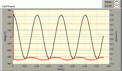 In this article I explain the inrush current phenomenon for cold lamps. This is the current that flows in a short time period just after switch on of the (grid)voltage. This current peak for an (led) light bulb is directly comparable to that of a motor. The inrush current measurement function of for instance a digital multi meter is for the lamp inrusch current not suitable.
The measurements on the inrush current at the measured lamps is done in a way that gives relevant info of the peak currents and a parameter is derived that is needed in selecting the correct fuses.
Inrush current, info
This is the current that flows in a short time period just after the first switch on of a cold lamp. With cold I mean that the lamp has been off for some time, enough to have the major capacitors and eventual coils emty with regard to energy.
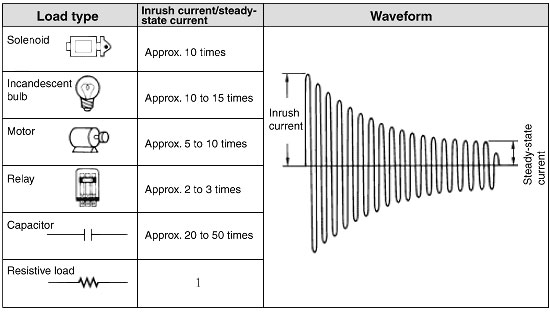
Inrush currents is a known phenomenon for (heavy) motors. These motors are inductive loads that during a relative long period of time (several cycles of the grid, sometimes up to 250 ms) can draw a current that is significantly higher than the steady state current. This higher peak current needs to be delivered by the power grid and fuses, switches and cables need to be able to handle this current without shutting down the application.
Image with typical (relatively) long lasting inrush current, enduring several grid cycles, coming from http://www.omron-ap.com/FAQ/FAQ02165/index.asp
Inrush current (led) lamps
For (led) lamps the inrush currnet is different than for (inductive loads like) motors. The peak is very much shorter in time duration (less than a single cycle) and therefore it needs to be defined how this peak is captured and how is made sure that a meaningful value is taken. Herewith a few real life examples of led lamps:
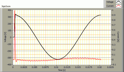
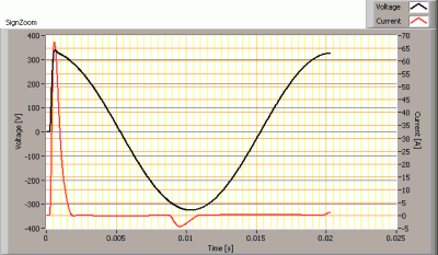
Inrush current for two different led lamps
The same inrush current but now zoomed during the first cycle only.
It needs to be defined how is measured. As the peak only takes a few ms, its max value on itself is possibly not that important. More important is to know how much energy in inside the peak. That amount of energy can be determined if the peak and its duration is capture accurately enough. Once this energy value is determined it can be compared to allowable (specification) values of fuses that are selected.
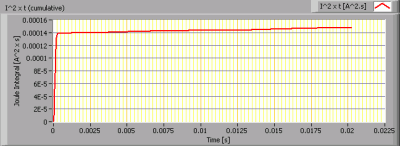
Energy values of the current during its first 20 ms (at 50 Hz this is equivalent to one cycle) expressed in Iˆ2.t (current squared times the time duration).
An other aspect that needs to be taken into account is the determination of the worst-case inrush current. A power voltage that at switch on starts from 0 and follows it sinsoid from there will most likely not result in a worst case current. A voltage that is switched on at its maximum value will, for capacitive loads, result in much higher inrush currents.
To determine the worst-case inrush current there is need to test a cold lamp at different voltage starting angles.
See below the different inrush currents at different voltage starting angles, starting from 0 degrees to 170 degrees with a step of 10 degrees.
Inrush currents at voltage starting angles from 0 to 170 degrees in steps of 10 degrees.
The worst case inrush current is, for (led) lamps, most often the one that comes when the voltage starting angle is at 90 degrees. OliNo reports in its measurement report at what starting angle the worst case inrush current has been measured.
Details of the inrush current measurement
The inrush current needs to be determined during its short time that it lastst. Therefore a sampling frequency of about 40 kS/s is taken. A Planck-Bessel window is used for the samples as we do not know the frequency of the signal and we do not want to introduce high frequency signals in our measured signal.
Then this sampled singal is fed through a low pass 2nd order Butterworth filter at 2 kHz. This low pass filter will remove any high frequency content that is not relevant for the inrush current. The Butterworth filter results in an equal time delay for the frequencies below 2 kHz therefore the current form will remain unaltered.
Every 10 degrees of voltage start angle the inrush current is measured, for voltage start angles from 0 – 170 degrees. Every measurement takes 2 seconds and then the lamp is switched off during two minutes before any nxt measurement is done. This time has been determined to be long enough to get rid of (most of) the internally stored charges in the capacitors.




27 replies on “Inrush current for (led) light bulbs”
Hi,
I’m at the planning stage of lighting my workshop with LED Lighting.
I need about 10 x 50w LED High Bay Lights. I plan to use a Honda inverter generator EU26i to power them.
Q. Will I run into problems with this setup because of the inrush load?
thanks, tony
Dear Tony. I have checked the specs of the inverter generator which is capable of 2800VA and a rated current of 12.2A. Your 500W should not be a problem for normal load. Then about the inrush current, when the led driver is not designed with inrush current in mind, you could expect a small peak of 5000W at the very 1 ms at the start. This is twice the rated output but however for a very small period of time, eg 1 ms.
I cannot find anything about inrush current capability in its specification but I would expet this not to be a problem.
And possibly the leds you mention have drivers that are better than the case I mention. In your case, I would expect it to function properly. However for sure I cannot say.
Good afternoon,
I plan on using a Steinel nightmatic 2000; http://www.steinel.de/en/Motion-Detectors/Photoelectric-Lighting-Controller/Photoelectric-lighting-controller-NightMatic-2000-Black.html to switch on a 30w led floodlight. Is it likely I will have a problem with inrush current as someone has mentioned I should use a contactor but I think this may be overkill? Any advice you can offer would be very much appreciated.
James
Dear James. I have looked at the spec of the Steinel device. It looks like it can handle a 1000W lamp when this lamp has a high power factor or 500 W when the power factor is 0.5. When considering a 30W LED floodlight then I expect the power factor to be not worse than 0.5. So that means that you should be able to handle 500 W with this device, whereas you only need 30 W to switch. No issue I would say.
Note that I use the power factor instead of the cos phi. The reason is that cos phi is deprecated. The cos phi does only account for a change of phase between the voltage applied and the resulting current flow. However in current day electronic devices with switched mode power supplies, we most of the time have no phase difference between the voltage applied (from the grid) and the current flowing, however the current can look quite different from a sinusoid (like the voltage) and a difference in form is also considered to be less optimal and the power factor accounts for that also (so, power factor accounts for a phase shift as well as a difference in form). Therefore, the power factor is more complete and more approriate to use for current day electronical devices. It also works for older devices which used mostly coils and inductors where only a phase shift was apparent.
Hi. I’m planning on replacing 12 BR30 incandescent bulbs on a single 20 amp breaker circuit with 12 Philips 9.5 watt LED bulbs. Will inrush load be a problem?
Thanks,
Nathan
Nathan, to get an indication of a possible inrush current of an E27 lamp of 10 W, look at our overview of light bulbs with E27 fitting and check for wattage. See this link to get an overview of all E27 bulbs with a power between 7 and 13 W. Look into the detailed measurement report to get an indication of possible inrush current.
Two parameters are of importance, the width of the peak and the heigth of it. Then knowning these two results, you should look for a known supplier of circuit breakers and check with them whether 12 loads can be connected to a 20 A circuit breaker.
In the Netherlands we have for instance Hager as a supplier. They have a webpage where they ask you to input the peak value in Ampere and the duration in microseconds and when filling these in, you get the max number of loads for a number of circuit breaker-types they sell.
Marcel,
Just as a heads up the inrush current can and does cause issue in inverters (including inverter based generators) if the peaks are over the design limits (including protection) and.
So, the guy with the Honda generator may over time, end up with damage especially if all the lights are turned on at the same time.
Please note that omron updated their web site and changed the FAQ to this link:
http://www.omron-ap.com/service_support/FAQ/FAQ02165/index.asp
(Added service_support in the URL)
Dear Sir, please help, when replaced 20 incandescent lamps with LED bulbs of 5w in a Chandelier, MCB is tripping at the moment of switching on. please advice do i have to change the MCB or any other way is there.
Dear Suryaprakash. It looks like the inrush current issue. Try an inrush current limiter. At Conrad I found devices that work for single appliances, see this example. This should then be applied for each load.
An other option is to select an MCB that is more tolerating. In the Netherlands, we use B16 (16 Amps, B-characteristic). There also exists C16, also 16 Amp but accepting higher current peaks. This Sunday I have a similar issue with a device in my sister’s house. It is a treadmill, and most of the times the device is switched on the circuit breaker in the central electricity box trips. This I want to prevent from re-occurring by using the mentioned device from Conrad. I can inform you whether it was successful or not.
Dear Suryaprakash, my sister told me that the device works! It is the device I gave as an example in my reaction nr 10.
Hi, how to calculate inrush current for LED ??
say if i am using 5 w LED what will be its inrush current??
if i have 1 amp trailing edge dimmer how many 5 watt led i can connect to single channel??
Hi Kartik, I do not know of a method to be able to really calculate an inrush current. This is because it really depends on the driver and the way it is built. Not the amount of LEDs neither their power they draw.
It is true however, that for LEDs the dimmer manufacturers assume that these have a relatively high inrush current. So if I have a 200W dimmer, then most of the time I see that one advices not to put more LEDs than for 50 W.
I have a project that has 5420 each 60W LED Fixtures. We are powering all on an emergency generator when the power goes out. currently the design place all fixtures on the generator at one time. sometimes it accepts the load other times the in-rush will kick the generator out. i need some help understanding what is going on. Generator is rated 600 kW, 480 VAC, running load appears to be 325 kW. Can you help?
Hi John, in the article I described a way how I meaningfully measure the worst case inrush current peak. Once you have the peak value and its width in microseconds, then your supplier of the generator might be able to tell you how much it can handle. It will have a continuous load defined and a short therm max load. Try to be below the defined short term max load specification.
You will probably have to use inrush current limiters in the output of the generator. One way is to use NTCsm but also active circuit can be used if “hot restart” capabilities are crucial. However for LED fixtures a hot restart would not result in a equally high inrush current peak as the LED-driver’s charges internally will not be empty.
I want to make driver for 30W street light driver.so could i use fuse to protect the inrush current..what should be the value of fuse.please answer me.
Hi SUVRA, the inrush current is a property of the driver that is used. When at the entrance of the driver you want to include a fuse then make sure that this fuse is big enough to allow the worst case inrush current, since otherwise the fuse might blow already when the inrush current flows. And as the inrush current is a normal property of the driver, this is not the way to solve for a too big inrush current.
If you want a certain maximum inrush current, make sure you select a driver with that property. You might want to inform at the driver-manufacturer.
When you have already some drivers with inrush currents that you find too high, or when you experience trips of circuit breakers when your lamps are switched on, then what you can consider is using an inrush current limiter inside the switchbox of a building or house. See for an example of such a device here.
Dear Marcel,
could you please explain in detail how your measuring device works?
As I think, there should be oscilloscope, but how do you connect it to 230V line? I assume it can be made using Hall effect sensor, but unfortunately I know too little in this field.
Dear Pavel. I am using the Agilent/KeySight 6813B programmable power supply. That device is capable of delivering the power and also it can measure the results.
Hi Marcel. Please, can you help me?
I want to use a timer with 2 relays (8A/250V/cos phi=1, each) to control 2 Osram Led floodlights (50W and 10W/cos phi>0.9) in 127V. I contacted the manufacturer of the timer and they insist that i need to use a contactor to switch these 2 small loads. I would like to drive it directly, because of the small load. Do you think that’s mandatory the use of 2 contactors in this case? Thank You.
Dear Ricardo, a contactor would be used instead of a relay, when switching > 10 Amps. It can better deal with arcs which could occur when switching inductive loads. Your load is <> 10 A. The supplier should be able to tell. It is not expected to last more than 300 microseconds though. But the supplier should also be able to tell the max inrush current. Could you find data on what maximum short lives current your relays could handle?
Hi Marcel, thanks for the answer.
There’s no information about the maximum inrush current that my timer can handle. I’ve made some tests and it works fine, do you think the worst that can happens is just the welding of the contacts? Cause I’ll stay 1 month off and i want it to turn on and off my lights. Do you think it’s safe? Thanks a lot.
I would go for your relay solution and would assume that you are safe.
Thanks for sharing the post. It’s a useful information for us.
Hello,
Do you think that inrush current on 230V can somehow damage Leds that are after the drivers.
We have the case of LED damaged (not the driver) in case of use of electronic switches (like detector or remote switch) with several drivers and leds.
For example: one detector with 3 flood lights or one remote controlled switch with 4 or five downlights.
LEDs get destroyed, not the driver.
Nicolas
The LEDs can be damaged when a peak in current or voltage is passing through the driver towards the output where the LEDs are. This means then that the driver itself is not built well enough to prevent these passes through.
I have had a customer that used LED lamps in a veranda. The LED lamps/modules were connected via long wires to the driver. There was a motorised obscuration system. This system was switched on when users wanted to generate shade. The peaks in current that this system generated on switch on and off and the fact that the LED modules had long wires able to pickup the peaks via magnetic coupling, made the LEDs deteriorate within months.
So, it can be that the own system’s inrush current goes through the driver but I do not assume this is the case. I would more expect a coupling issue of high currents from one driver onto the wires going to LEDs of the other driver.
Hi. I see that you don’t update your website too often. I know that writing articles is time consuming and boring.
But did you know that there is a tool that allows you to create
new articles using existing content (from article
directories or other pages from your niche)?
And it does it very well. The new articles are unique and pass
the copyscape test. You should try miftolo’s tools