BigMama, the OliNo lamp measurement tool
Posted by Marcel van der Steen in ExplanationTags: light Add comments
After seven months of work, from Feb 2008 to Aug 2008, she is finally born: BigMama! And it is her enabling OliNo to position accurately and repetitively the lamps that need to be measured. Together with some important other measurement tool this forms a flexible and fully automated test environment where a lot of interesting lamp parameters are measured.
The lamp positioning
The lamp to be measured will be mounted on the round disk. This round disk can turn and herewith the lamp can be turned around its own axis. This is what is called the turn angle and it can have a value from 0 to almost 360 degrees.
The disk is mounted on a frame that can incline this disk. The inclination angle can go from 0 to 90 degrees, with 0 the disk in vertical position and 90 degrees in horizontal position.
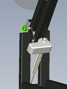
By using a linear motor the inclination angle is set. At a specific position a position sensor is placed, that measures the inclination angle.
Inclination angle sensor (in green) and the linear motor (in white).
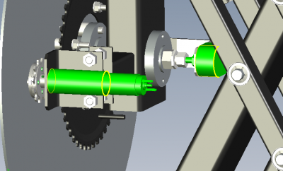
With a small DC motor the turn angle is set. A set of toothed disks, connected with a chain, is used to transfer the turn movement from the small motor to the disk.
Here also a position sensor is used that is connected to an extension of the disk axis.
The turn angle position sensor at the right and in front-left hte DC servomotor (both in green).
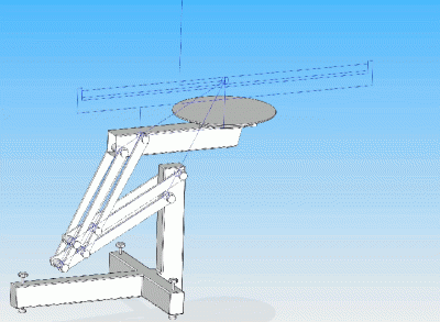
Fixed mechanical point
Different inclination positions and the stable mechanical point (click on the image).
As can be seen on the animated drawing, there is a specific position that remains on the same spot, for every inclination angle (and as well for every turn angle). It now is important to position the lamp’s lightspot exactly in this point. The light measurement sensor will be pointed towards this stable point. So by changing the inclination and/or turn angle, the light measurement sensor will be looking at the same lamp’s light point, albeit under different inclination and turn angles.
As a summary: the lamp is mounted on the turnable disk, such that its light spot’s position is the same as the position’s tool stable spot that is independent from any angle. At this moment the lamp can be turned over 360 degrees and inclined over 90 degrees. A well positioned light measurement sensor will then be able to measure light properties from this lamp under different turn and inclination angles.
Mounting of the lamp to be measured
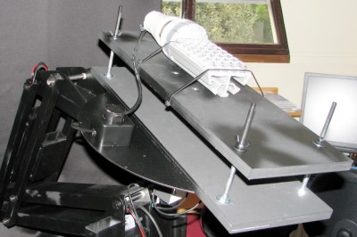
It is important to mount the lamp well on the turnable disk, such that its light spot is the same as the tool’s stable spot. For this, a shelf is fixed on the turnable disk with in every corner an M8 hole. Bolts of M8 or threads of M8 are used that are put through these holes and fixed with nuts. The thread ends are pointing outwards, away from the turnable disk.
An other shelf of the same sizes and M8.5 holes in every corner, is used to mount the lamp on. This shelf is then positioned over the thread ends and with nuts its height can be easily and accurately adjusted such that the lamp’s light spot coincides with the tool’s stable spot.
A mounted lamp on the BigMama. The lamp is mounted on its own shelf that is positioned at a certain distance above the base shelf that is fixed on the turnable disk.
By reserving a shelf for every type of lamp and lamp fitting the positioning of different lamp types can be easily and quickly prepared.
FL (Fluorescent Light) tubes can also be mounted and positioned easily; a normal shelf is used and the FL tube holder is mounted to this shelf.
A mounted FL tube on the BigMama.
Switching and setting/correcting the lamp voltage
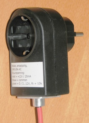
At a start-up measurement, where a cold lamp is switched on and immediately a number of parameters are measured continuously while the lamp warms up, it is needed to switch on the lamp. For this a device is made that can switch on and off voltages with help of a small driving signal.
The switch unit for switching the lamp voltage with help of a small voltage signal.
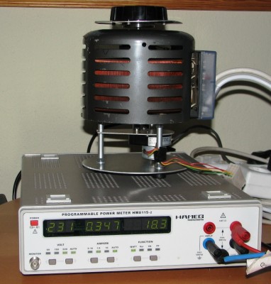
The lamp voltage can be set and corrected with a number of components. A variac is used that can transform a 230 V grid voltage to anywhere between 0 and 260 V (by turning a knob of this variac). A stepper motor drives this variac. A power measurement device is used to measure the voltage coming from this variac. This voltage finally is fed to the lamp, hence lamp voltage.
A program on the computer queries the lamp voltage from the power measurement device. The difference between the desired lamp voltage and the actually measured one, is used to drive the stepper motor a number of steps in the correct direction, such that the requested voltage is obtained.
At the top the variac, below the stepper motor and at the bottom the power measurement device.
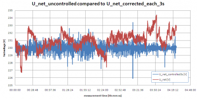
This cycle of querying the lamp voltage and correcting it to the desired value, is done once per 3 seconds. This corrects the slow voltage variations of the grid.
Grid voltage variations, and the effect of the correction once per 3 seconds.
As can be seen, the slow variations of the grid voltage are removed effectively. The short term variations are still present, but will never last longer than 3 seconds. As the light measurement time is normally in the range of 10 – 60 seconds it is fast enough to correct for grid voltage changes once per 3 seconds.
When 12 V lamps are to be measured, a 12V-transformer is used. This is positioned after the variac. The power meausurement device measures the voltage after this 12 V transformer. When a deviation from the requested lampvoltage is seen, the correction mechanism works the same; the stepper motor is driven to perform a number of steps in the correct direction that results in the requested voltage after the 12 V transformer. So, a different correction factor is used than there is without the 12 V transformer. The output voltage (secondary voltage) of the transformer is fed to the lamp.
Measuring Volt, Current, Power and Power-Factor
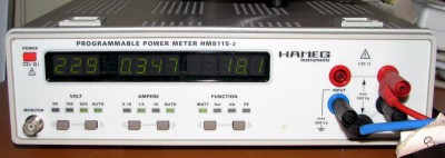
The power measurement device does all this
The power measurement device, fltr te lamp voltage U, lamp current I and power P.
The power factor can easily be calculated by using the formula: PF = P / (U x I).
Measurement of light parameters
With help of a spectro radiometer various interesting lamp characteristics are measured. These are:
– Color Temperature [Kelvin]
– Color Rendering Index [-]
– Illuminance [lux]
– Spectral Power Distribution [W/nm/m^2 or W/m^3], over the wavelength area between 380 – 780 nm, and for each wavelength set of 5 nm the power is measured.
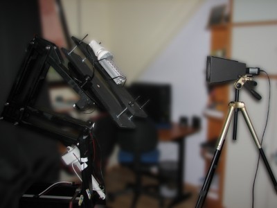
This spectro radiometer is positioned on a firm tripod, and aligned with the stable position of the positioning setup.
At the right the spectro radiometer on the tripod, directed towards the light spot of the lamp, which is the stable fixed spot of the positioning device.
Measures against stray light and reflected light
It is important that all light not coming directly (without reflection) from the lamp in measurement, does not reach the light sensor. So the light of the lamp that is reflected via walls, shall not reach the sensor. Neither the light from other sources such as the sun, or the lamps inside a room.
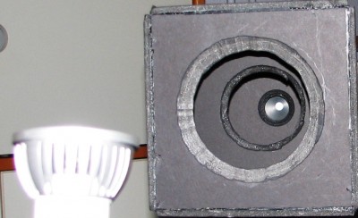
For this a sort of horn is made that is mounted in front of the spectro radiometer sensor. This horn has some baffles inside to keep all light out which comes in at a certain minimum angle (which then is not light directly from the lamp but must be reflected light or light from other sources).
Horn mounted around sensor, with baffles, to remove stray and reflected light.
The positioning setup as well as the shelves are all painted in matte black, so it does hardly reflect any light coming from any light source.
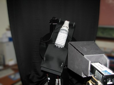
Behind the positioning tool a black curtain is put that has a size wide and high enough such that the sensor’s field of view falls within its dimensions.
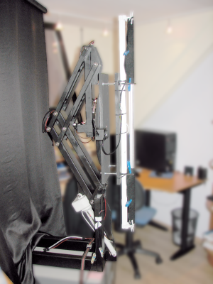
The horn on the spectro radiometer sensor and the black curtain behind a black positioning tool.
Temperature measurement
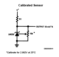
Two temperature sensors of the type LM355 are used. These are accurate, within 1 deg C. The following scheme is used to calibrate the devices.
The scheme around the LM335 temperature sensor.
The ambient temperature is measured with help of these sensors. If needed, one of these sensors can be attached to the light bulb in measurement to measure the temperature of the housing (without using BigMama’s movements).
Automating the whole
All components are driven from a computer.
A data acquisition card is used to interface with the three motors (inclination, turn, and variac lamp voltage), with the the position sensors, with the voltage switch and the temperature sensors.
The power measurement device and the spectro radiometer have their own USB connection with the computer to drive and query these.
The measurement program on the computer can read scripts. These scripts contain commands and parameters that are executed one after the other. The commands are used to drive all components, to perform the logging of the received measurement results and to perform analysis on the results.
It is possible to create additional commands in the program, after which these commands can be used in scripts giving additional functionality to the whole setup.
Conclusion
With BigMama Olino has now a measurement tool that enables many and accurate measurements on a big diversity of lamps.
At the same time the tool is well extendable thanks to its flexible program.



Most popular posts